Contact Us
26041 Newton Circle
Elko New Market, MN 55020
ndsdrillingsupply@gmail.com
1-800-637-1940
(952) 461-3400
(952) 461-3403 (fax)

Hammers and Hammer Bits
Hammers
NDS Drilling Supply sells the “P” Series Eastern hammer. This hammer is designed to drill under large volumes of water. We also sell the “BB” Series Eastern hammers. This is a high performance hammer designed for speed and reliability. And finally, we sell the Drill Series Eastern hammers, which is the legacy hammer. General Maintenance Manual for Drill Series and Competitor Series Hammers.
Bits
NDS Drilling Supply, Inc. sells many top quality bits in the following shanks: NDS Shank Sizes. They range in size from 3-3/4″ to 12-1/2″. Call for a complete list of current bits and sizes. Our bits are made with top quality carbides available in various shapes and sizes. NDS Drilling Supply, Inc. products are used by companies who demand top performance and reliability in the Geo-thermal and Water Well Industries.
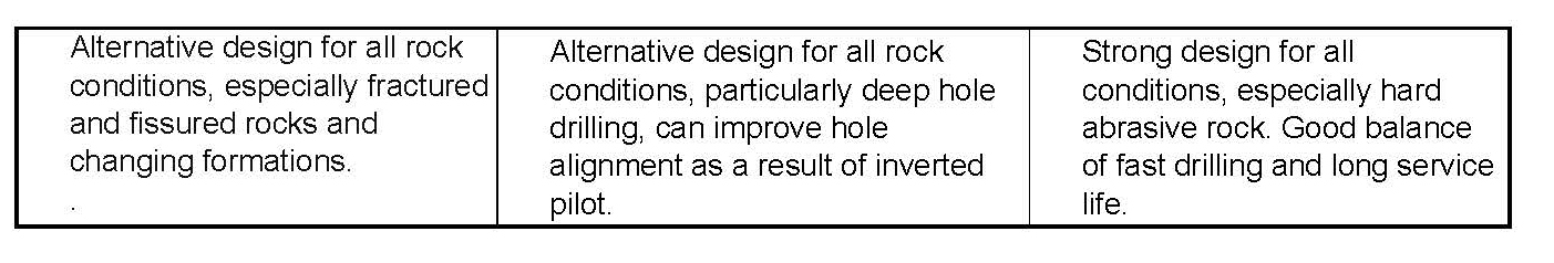
Head Designs
 Flat Head Flat Head |
 Concave Head Concave Head |
 Convex Head Convex Head |
SETTING UP THE DHD
DHD SETUP
Before the DHD is used to drill it should be set up for proper air consumption and the joints should be tightened. The selection of choke size and/or valve lift will be dependent on the hole cleaning requirements and the capacity (pressure and flow) of the compressor being used. Hammer air consumption should be set up for the best balance of power and hole cleaning. Other factors which need to be considered are the depth of hole, water to be encountered and water to be injected. In some cases, where such factors are unpredictable, the proper choke size can only be selected after experience is developed.
VALVE, CHOKE SELECTION, AND HYDROCYCLONE SETUP
The best performance of any DHD will be achieved when a maximum volume of air can be passed through the drill with a solid choke. under ideal conditions the pressure required to drive this volume through the drill will be within the capabilities of the compressor. All Quantum Leap DHD’s have a choke plug which can be changed for additional hole cleaning capacity if additional hole cleaning air is needed and compressor capacity is sufficient.
Bailing Velocity Requirements
The need for adequate hole cleaning cannot be emphasized enough. A hole that is not cleaned properly can result in poor performance, rapid wear of bits and accessories and in some cases loss of the drill and pipe down the hole. Hole cleaning is usually directly related to what is called bailing velocity or the speed of the air which is lifting cuttings from the hole.
Bailing velocity is defined as the velocity of the air in the hole annulus at atmospheric pressure. In other words, the effect of bottom hole pressure is not taken into account when computing bailing velocity. For conventional hole cleaning (no soaps or foams) bailing velocity should exceed 3000 ft./min. (914.4 m/min.). However, if possible, bailing velocity should not exceed 7000 ft./min. (2133 m/min.).
Bailing velocity can be computed by dividing the air consumption of the DHD in scfm by the annulus area in square feet. The equation following may be used:
Velocity [ft./min..] (m/min.) = Air consumption [scfm] (m³/min.)
Annulus area [sq. ft.] (sq. m)
where:
- Air consumption is the rated delivery of the compressor or the air consumption of the drill at maximum pressure, whichever is less.
- Annulus area is the area between the hole bore and the drill rod. It can be computed as follows:
- Annulus area [sq. ft.] = .0055 x (hole dia. [inches]2 – rod dia. [inches]2)
(sq. m) = .785 x (hole dia. [m]2 – rod dia. [m]2)
The sections following explain how to adjust the choke or valve to increase air consumption.
BIT INSTALLATION
Bits splines should be well lubricated with rock drill oil or thread grease before the chuck is installed over the splines. Additionally, the threads on the chuck should also be coated with thread grease before threading the chuck into the DHD. Remember to install the bit retaining ring halves before threading the chuck into the DHD.
New Bit and Chuck
All QL drills (except the QL200) use tapered retaining rings which are locked in place axially and radially when the chuck is tightened. This patented feature insures lower end drill parts are held securely in place to prevent vibration and movement. Be careful not to get flat retainers from earlier model DHD’s mixed with the tapered rings. The QL120 and QL200 use plastic drive pins which insure a non-metallic chuck to bit interface. These pins must be installed properly with the pin end labeled “TOP” (QL200 only) being visible after installation. The QL120 and QL200 pin drive systems have been designed so that if the pins are omitted, or fail, the chuck bit and spline drive surfaces can operate reliably for a short period of time.
Used Bit and Chuck
Caution must be used when installing a new bit on a used chuck or visa-versa. Some applications, usually soft rock where there is excessive bit travel within the splines, can develop uneven wear on the bit and chuck splines. When a new bit is installed within a used chuck there is likely to be poor mating surfaces. Check the condition of the chuck or bit splines when using a new bit or chuck if your application is prone to this form of spline wear.
It is also suggested that the chuck be rotated relative to the bit splines from time to time to even out the gouging and grooving which takes place due to erosive wear. This practice will extend your chuck and casing life.
MAKEUP TORQUE AND BACKHEAD CLOSURE
The Quantum Leap drills have two forms of locking means for internal components; the QL4 and QL200 use relatively low-load belleville springs, all others use “solid clamping” arrangement whereby parts are held in place under very high load.
Rotary head torque is usually sufficient to close the QL4 backhead. The QL200 uses a special wrench to close the backhead. However, because of the high load used to clamp the parts in place in the QL40, QL50, QL60, QL80, and QL120; a high level of torque is needed to close the backhead gap. Rotary head torque may be sufficient but in some cases a supplementary wrench may be needed. It is extremely important that the backhead gap be closed in these drills.
THE PRESENCE OF A GAP BETWEEN THE CASING AND THE BACKHEAD WHILE DRILLING WILL INCREASE THE CHANCES FOR LOOSENING THE BACKHEAD IN THE HOLE AND POSSIBLY LOSING THE DRILL.
In addition to at least closing the backhead gap, it is also suggested that the backhead and chuck be torqued to approximately 750-1000 ft. -lb per inch (40.5 – 54 N-m per mm) of hammer diameter. For example a 5 in. (127 mm) class DHD (QL50) should be torqued to 3750-5000 ft. -lb (5143.5-6858N-m). This makeup torque insures against loosening joints in the hole and also preloads the threads sufficiently. Refer to Figure 6 of Section 5 for makeup torque specifications.
DRILL LUBRICATION
LUBRICATION GUIDELINES AND SPECIFICATIONS
Effects of Corrosion
Drillers must be aware that damage to a hammer’s parts occur do to the lack of correct lubrication, the lack of maintenance and storage of the hammer without protection rather than from normal wear and tear from drilling operations.
All DHD’s require oil lubrication to resist wear, galling and corrosion. Additionally, the film of oil coating all internal parts seals internal clearance paths to reduce power-robbing leakage across sealing clearances. As a general rule of thumb the oil required is proportional to the volume of air being used.
Oil also needs to be of sufficiently high quality. It is recommended that Ingersoll-Rand rock drill oil be used. If another type of oil is used it must comply with the oil specifications shown in Figure 3 of Section 5.
For dry drilling (less than 2 gpm (7.6 lpm) of water injection) it is generally recommended that oil be injected into the drill air stream at the rate of 1/3 pint (.16 l) of oil per hour for every 100 scfm (2.8 m^3/min.) of air. For example a 900 scfm (25.5 m3/min.) compressor delivering full flow to a DHD would require 900 / 100 x 1/3 = 3 pints per hour (25.5 / 2.8 x .16 = 1.6 l per hour). For wet drilling (more than 2 gpm (7.6 lpm)), and in particular when using a Hydrocyclone water separator, it is suggested that the lubrication rate be doubled to 2/3 pint (.32 l) of oil per hour every 100 scfm (2.8 3/min.) of air. The additional oil compensates for the wash-out caused by water and the oil losses caused by the Hydrocyclone.
Lubricators
There are two primary types of lubricators; a plunger oiler and a venturi oiler:
A plunger oiler normally operates from a timed plunger system which delivers a fixed “slug” of oil into the line in timed intervals. These systems are beneficial in that the oil reservoir does not need to contain a high pressure. Plunger lubricators are also insensitive to oil viscosity and temperature. However, because of the complexity, the reliability of plunger lubricators is not as good as the venturi type. Also, because oil is delivered as “slugs” it is not atomized and delivered to the drill internals as evenly as a venturi.
Venturi type lubricators (sometimes referred to as pig oilers) operate in a similar fashion to a gasoline carburetor. A necked down area in the venturi creates a pressure drop which draws oil into the air stream. the oil is atomized and mixed very efficiently with the air providing maximum coverage and cohesion to internal drill components. A needle valve is usually used to adjust the oil volume delivered. Disadvantages of the venturi oiler are that it requires a pressurized volume, which is generally small in volume. Also, the lubrication rate is dependent on oil viscosity which varies with temperature.
LUBRICATION CHECK
When oil is injected into an air stream with dry piping or hoses it takes a considerable amount of time to coat the walls of the piping so that the oil is actually delivered to the DHD. Until these surfaces are coated with an oil film very little is actually delivered to the DHD. It’s important to insure that an oil film is established before starting the DHD. It’s recommended that the drill be allowed to blow until a visible film of oil is developed on the bit blow holes.
Placing a piece of cardboard or wood beneath the blow holes gives a good indication when oil is passing through the drill. The cardboard or wood will become wet with oil when an adequate film of oil has been developed. If a drill string has not been used for some time and the oil has dried out it is suggested that a cup of oil be poured into each rod to assist in developing an oil film. After drilling with high levels of water injection it is important to note that any film has probably been washed off. For operators that switch from wet to dry drilling (i.e. water-well and quarry) its important to redevelop the oil film.
WATER INJECTION
Water injection can cause a DHD to either consume more air (hold a lower pressure) or less air (hold a higher pressure) depending on the volume of fluids injected. For example, if a DHD is lubricated with oil and water is then injected at a low rate (less than 1 gpm (3.8 lpm)), the oil film which is sealing the internal leak paths is washed out and air consumption will increase (pressure will fall).
Conversely, if water is injected at a high rate (more than 3 gpm (11.4 lpm)) the fluid level will be sufficient to seal the leak paths and restrict the flow of air through the DHD. In this case the air consumption will decrease (pressure will increase).
The pressure rise associated with water injection can sometimes exceed the maximum pressure rating of a compressor. In these cases the choke or Hydrocyclone bypass hole must be increased to reduce pressure.
The use of water, while required in most cases, does reduce component life. The following lists some of the problems that water injection can cause:
- Poor quality water can either be corrosive or can carry contamination into the drill. Premature wear or corrosion related failures can result. All water injected into a DHD should be neutral in pH and free from particulate contamination.
- Water injection reduces drill performance considerably. Water restricts the flow and resultant pressure in working chambers of the drill and reduces face cleaning which causes regrinding of cuttings.
- Water present at the impact face causes cavitation of the bit and piston and jetting or cutting of the exhaust tube. In both cases component life is reduced.
A DHD that has been operated with water injection and will idle for more than a few days should be dried out and lubricated with oil. This can be accomplished by blowing lubricated air through the tool when drilling is finished.
QL60 NON-LUBE INSTRUCTIONS
The QL60 non-lube does not require injected oil or other lubricants. However, the use of oil will not harm the DHD. The following operational considerations are required.
- A minimum of 1/4 gpm (1 lpm) of water is needed to lubricate and cool the internal seals. It is suggested that at least a “mist” of water be used even while driving casing.
- Use of the QL60 no-lube for quarry applications is not recommended unless;
- The minimum water injection rate is observed, and,
- The chances of getting stuck and overheating the drill are minimal. The addition of frictional heat can be sufficient to melt the piston seals and bearings.
- A hydrocyclone can be used on the QL60 non-lube. Sufficient water bypasses the Hydrocyclone to permit adequate cooling of the seals and bearings.
- Because there is usually no oil present in the QL60 non-lube to prevent corrosion, it is important to oil the DHD if it will be idle for more than two weeks. The following process is suggested.
- While the cylinder and casing have been specially heat treated to resist corrosion, other internal parts need the protection of oil when not being used.
- Fill the backhead bore, or last joint, with approx. 1 pint of oil (motor oil if fine),
- Re-connect and cycle the drill on a block of wood at low pressure (50-100 psi) for approx. 15 seconds.
ROTATION SPEED
Rotation speed directly affects the amount of angular index the bit inserts go through from one impact to the next. The optimum amount of index is dependent on variables such as blow energy (pressure), rock hardness, bit diameter, etc. The ideal rotation speed produces the best overall balance of penetration rate, bit life and smoothness of operation. It generally occurs when cuttings are their largest.
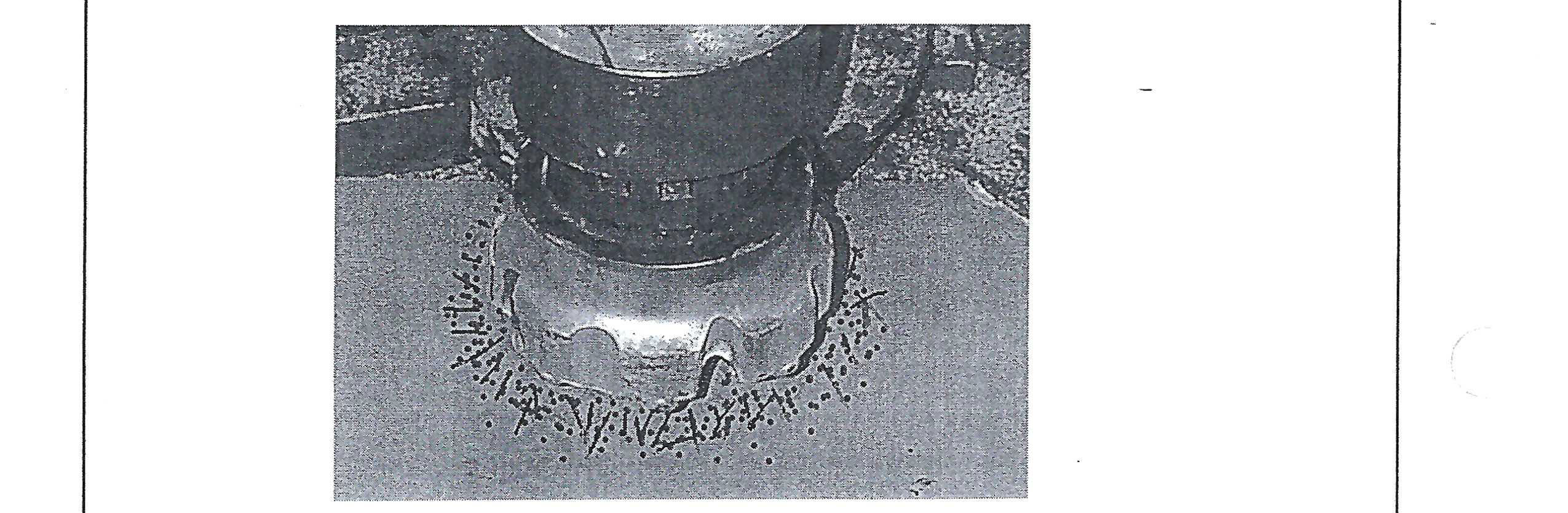
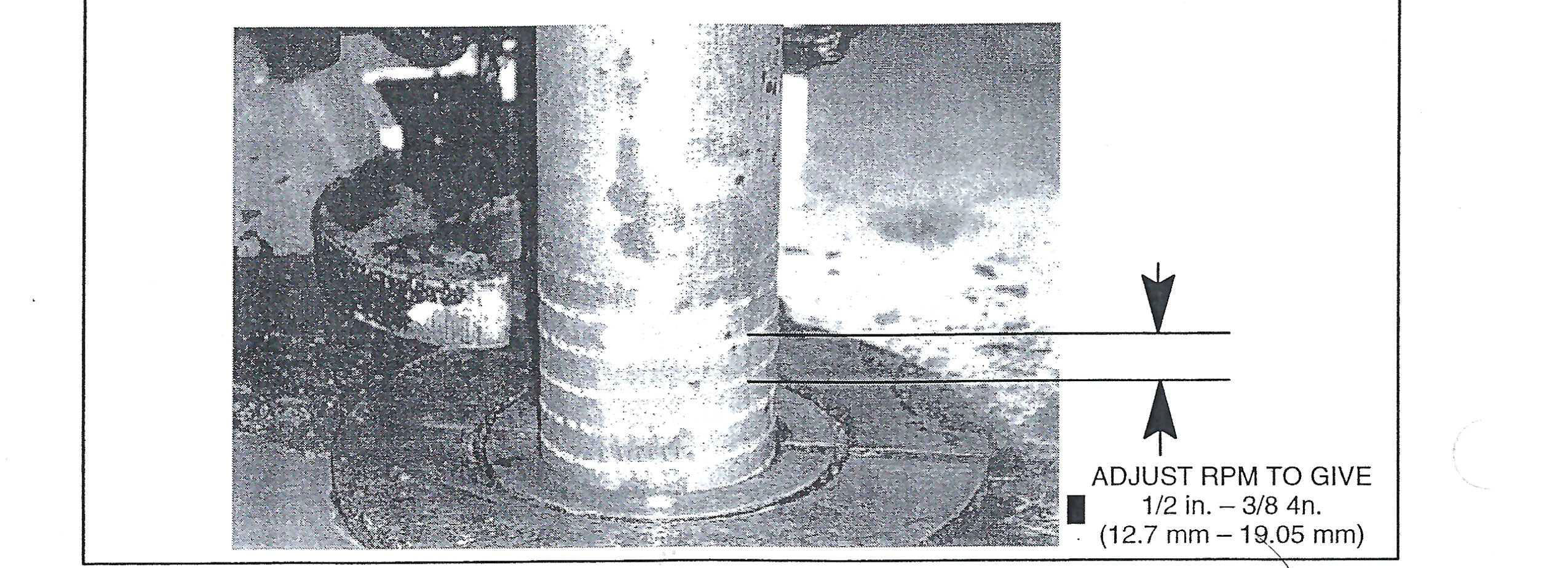
Determining the optimum rotation speed needs to be carried out in the actual application. A good rule-of-thumb is to divide 300 by the bit diameter in inches to determine RPM. This will get the rotation speed in the “ballpark” However, a fine-tuned rotation speed also needs to be correlated with penetration rate. It has been found that a proper rotation speed usually results in a 3/8 in.- 5/8 in. (9.525 mm – 15.875 mm) advance of the bit per revolution of the DHD. This measurement can normally be taken by using chalk or soapstone to scribe a spiral on the drill pipe while the drill is operating. The distance between the spirals (thread pitch) can be measured to determine if rotation speed should be increased or decreased. Obviously, if the pitch is less than 3/8 in. (9.525 mm) the drill RPM should be decreased, if it is more than 5/8 in. (15.875 mm) the drill RPM should be increased.
The picture following shows an example of the marks left on a drill pipe when using chalk to mark the advance of the drill.
Another method for setting rotation speed involves witnessing the wear flat developed on the carbide. The wear flat should be directly on top of the inserts. A flat which is on the leading edge of carbide (side facing the direction of rotation) indicates rotation speed is too slow. Conversely, rotating too fast will cause rapid wear of the bit and the wear flat will be on the trailing edge of the carbide.
Note that due to the higher penetration rate of Quantum Leap drills over conventional valveless drills, rotation speed will normally need to be increased proportion to the increase drilling speed.
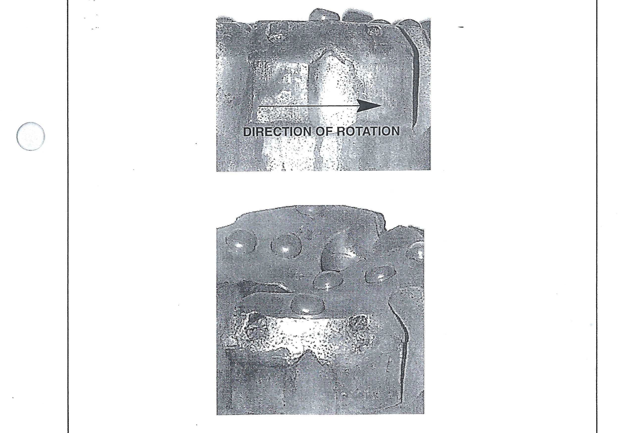
VIEW SHOWING WEAR FLAT ON LEADING EDGE – INDICATES ROTATION TOO SLOW. NOTE THAT CARBIDE FAILURE WAS CAUSED BY THE LEADING EDGE WEAR FLAT.
COLLARING
Collaring a drilled hole is a critical stage of the drilling process. In blast holes it can determine the quality of the top of the hole and the ability to load a charge. In foundation and well drilling it can determine the overall straightness of the completed hole. It is suggested that a drill be collared with low pressure and feed until the hole has stabilized. Just as a twist drill needs to be controlled carefully when drilling with an electric hand drill, a DHD needs to be started with care.
FEED FORCE (hold down and hold back)
The force required to feed a percussive tool properly is directly proportional to the level of output power.
As a rule of thumb, DHD’s need to be fed with a force of roughly 500 lbs per inch (9 kg per mm) of hammer diameter when operating at maximum power.
In many cases operators will simply adjust the feed pressure until rotation pressure starts to pulse and then back off slightly until rotation pressure becomes smooth. When a hole is first started, if the weight of the starter rod or collars is not sufficient to feed the drill then pull down will be needed. As the hole is advanced and more weight is added to the drill string, the level of pull down will need to be decreased. Eventually, the weight of the string may exceed the proper feed force and the feed system will need to be shifted to a pull-back mode.
When drilling through varying conditions such as hard and soft or voided material, every effort should be made to keep the drill fed properly. A loose running DHD can cause damage to the tool and bit in a short period of time. The feed system of a drilling rig should have a sufficiently fast response so the DHD can “catch up” with the bit when a void or soft seam is encountered.
As with rotation speed, Quantum Leap drills will typically need to be fed harder due to their higher output power level over valveless drills.
It’s equally important to avoid feeding too hard through voided and fractured material. The piston in a DHD operates within the casing with a clearance of about .003 in. (.076 mm) on each side. While the casing appears very strong and stiff, it does not take much sideways pressure to distort the casing enough to cause interference with the piston as it reciprocates. If the casing is overfed through voided ground it is likely that deflection of the casing will occur. Frictional cracks will develop on the surface of the piston if the piston rubs hard enough against the wall of the casing while being distorted. These small frictional cracks can eventually grow and break the piston.
Feed force should be reduced when drilling through voided, unconsolidated or fractured ground to avoid twisting or distorting the hammer casing.
HOLE CLEANING, FLUSHING AND DUST SUPPRESSION
As stated previously, the importance of good hole cleaning cannot be over emphasized. A hole which is not cleaned effectively will cause reduced production (penetration rate), decreased bit and accessory life and could ultimately increase the risk of losing the drill & string in the hole.
DRY DRILLING
The most effective means for hole cleaning is drilling dry. Cuttings are normally lifted and cleaned from the hole very efficiently. Imagine blowing, or sweeping, dust or dirt from a floor when the floor is dry and wet… which is more effective? The same principle holds true for cleaning cuttings from a hole.
WET DRILLING
Water injection is required in many applications for dust suppression or hole cleaning. Water injection rates for dust suppression only are usually less than 1 gpm (3.785 lpm) and just sufficient to moisten fine dust. It is usually common to use minimal water injection for dust suppression in shallow blasthole applications where water intrusion into the hole is not a problem.
Heavier volumes of water injection are usually required in water well and deep-hole applications where a number of factors come into play;
- Water intrusion into the hole can develop mud rings where dry cuttings meet a seam of water entering the hole. Mud rings develop where dry cuttings stick to the wall of the hole when they hit the moist area. Water injection is needed to keep the hole wet enough to prevent these mud rings from developing. Fluid injection rates can vary from 2-15 gpm (7.57 – 56.775 lpm) depending of the hole size, rate of penetration and the type of material being drilled.
- Some materials such as those which drill fast or contain clay can sometimes require very heavy levels of water injection. These applications are unique in that they can either be drilled totally dry or totally wet….not in between. Marginal fluid injection results in making a tacky mud which sticks to the drill rods and hole wall and hinders hole cleaning. The correct level of fluid injections thins the paste so it will be cleared from the hole.
WET DRILLING WITH HYDROCYCLONE
Many of the compromises associated with water injection are eliminated when using a Hydrocyclone water separator. With the Hydrocyclone, as much water as needed can be injected without a significant loss in performance. The Hydrocyclone will typically remove approximately 98% of the fluids injected until the bypass orifice becomes saturated and cannot pass any more water.
If the Hydrocyclone bypass orifice is not large enough to pass all the fluid being injected, the remainder of fluid will pass through the drill as if the Hydrocyclone was not present. However, a portion of the benefits associated with using the Hydrocyclone will be lost. If this does occur it is suggested that the bypass orifice within the Hydrocyclone be enlarged to pass the additional volume of fluid. See previous paragraphs and table involving Hydrocyclone setup.
Because the Hydrocyclone removes matter that’s heavier than air, it removes rust scale, small rocks and other debris in addition to fluids. As a result, the Hydrocyclone can become clogged with debris. It is suggested that after every hole, the ports in the Hydrocyclone backhead are checked to be open. This can be determined simply by witnessing the passage of air or fluid through ports while blowing air. If they are clogged refer to the service and maintenance section for repair instructions.
Insure Hydrocyclone backhead ports are passing air at the end of each hole.
REMOVING THE DRILL BIT
Bit removal can be one of the most dangerous and frustrating tasks associated with the drilling operation. However, with the proper tools and techniques it should require no more than a few minutes and few expletives to remove a bit. The following lists pointers which will be beneficial in helping you remove a bit quickly, safelt and with reduced risk to damaging DHD parts and components:
- Use sharp tong jaws. Worn or rolled over tong jaws increase the jaw pressure and make the wrench more prone to damaging the hammer case. Many Ingersoll-Rand hammer cases are case hardened which means sharp jaws are needed to grip through the hardened case.
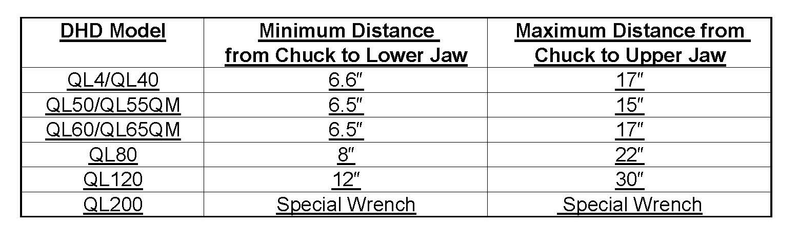
- Grip the casing in the proper location. Gripping over the threads can make thread loosening extremely difficult. Example; as the wrench tightens it exerts an inward force which can pinch the threads if they are under the wrench jaw. This only increases the torque needed to uncouple the thread. Also, do not grip the casing in an area where the bore is not supported by either the piston or bearing. Gripping over an unsupported area can distort the bore. The figure and table below shows the recommended locations for wrenches.
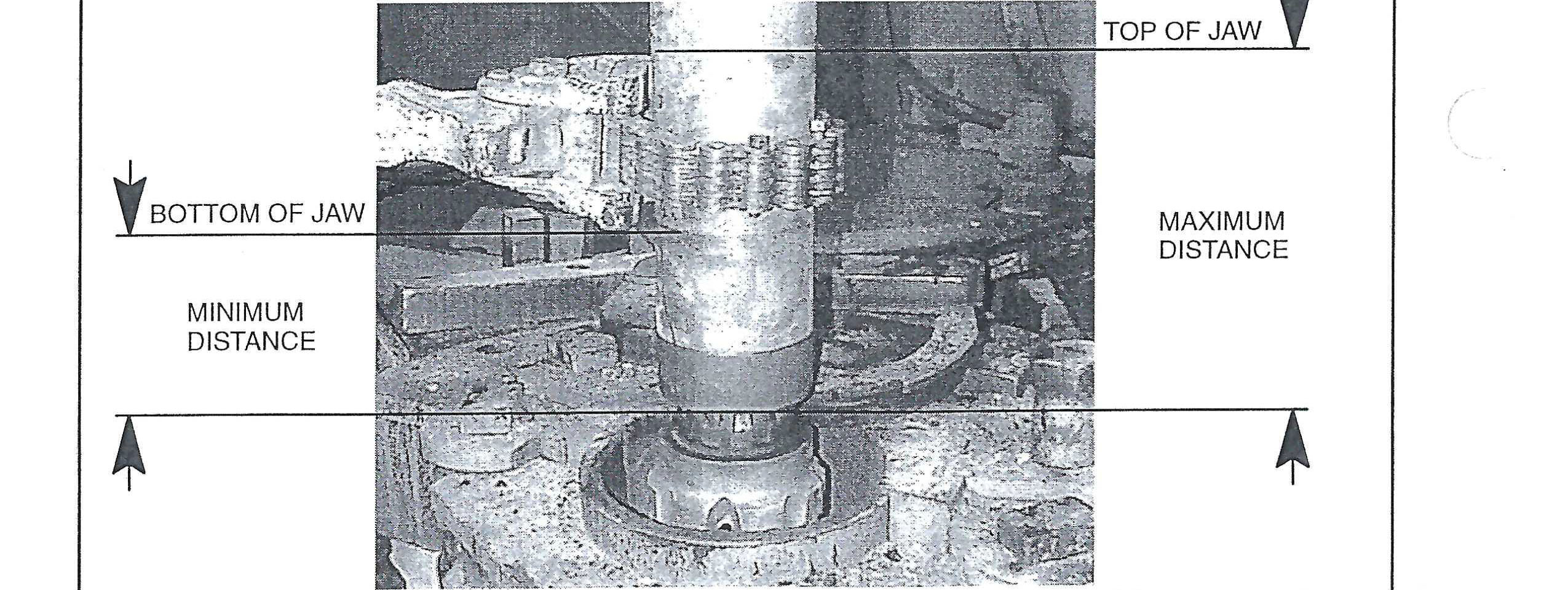
Chain Wrench Positions